|
 |
Concentrating Solar Power (CSP) Technologies
Concentrating Solar Power (CSP) technologies use mirrors to concentrate (focus) the sun's light energy and convert it into heat to create steam to drive a turbine that generates electrical power.
CSP technology utilizes focused sunlight. CSP plants generate electric power by using mirrors to concentrate (focus) the sun's energy and convert it into high-temperature heat. That heat is then channeled through a conventional generator. The plants consist of two parts: one that collects solar energy and converts it to heat, and another that converts the heat energy to electricity. A brief video showing how concentrating solar power works (using a parabolic trough system as an example) is available from the Department of Energy Solar Energy Technologies Web site.
Within the United States, CSP plants have been operating reliably for more than 15 years. All CSP technological approaches require large areas for solar radiation collection when used to produce electricity at commercial scale.
CSP technology utilizes three alternative technological approaches: trough systems, power tower systems, and dish/engine systems.
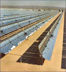
Trough Systems
Trough systems use large, U-shaped (parabolic) reflectors (focusing mirrors) that have oil-filled pipes running along their center, or focal point, as shown in Figure 1. The mirrored reflectors are tilted toward the sun, and focus sunlight on the pipes to heat the oil inside to as much as 750°F. The hot oil is then used to boil water, which makes steam to run conventional steam turbines and generators.
 Click a photo below to view interactive panoramas of parabolic trough facilities. Click a photo below to view interactive panoramas of parabolic trough facilities.
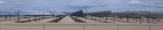
SEGS IX Parabolic Trough 360° - Interactive Panorama. Source: Argonne National Laboratory
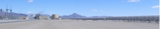
Nevada Solar One Parabolic Trough - 360° Interactive Panorama. Source: Argonne National Laboratory
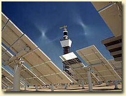
Power Tower Systems
Power tower systems also called central receivers, use many large, flat heliostats (mirrors) to track the sun and focus its rays onto a receiver. As shown in Figure 3, the receiver sits on top of a tall tower in which concentrated sunlight heats a fluid, such as molten salt, as hot as 1,050°F. The hot fluid can be used immediately to make steam for electricity generation or stored for later use. Molten salt retains heat efficiently, so it can be stored for days before being converted into electricity. That means electricity can be produced during periods of peak need on cloudy days or even several hours after sunset.
Click the photo below to view interactive panorama of a power tower facility.
eSolar Sierra Suntower Power Tower Facility - Interactive Panorama.
Source: Argonne National Laboratory
Dish Engine Systems
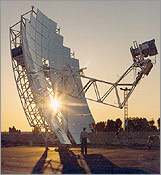
Dish/engine systems use mirrored dishes (about 10 times larger than a backyard satellite dish) to focus and concentrate sunlight onto a receiver. As shown in Figure 5, the receiver is mounted at the focal point of the dish. To capture the maximum amount of solar energy, the dish assembly tracks the sun across the sky. The receiver is integrated into a high-efficiency "external" combustion engine. The engine has thin tubes containing hydrogen or helium gas that run along the outside of the engine's four piston cylinders and open into the cylinders. As concentrated sunlight falls on the receiver, it heats the gas in the tubes to very high temperatures, which causes hot gas to expand inside the cylinders. The expanding gas drives the pistons. The pistons turn a crankshaft, which drives an electric generator. The receiver, engine, and generator comprise a single, integrated assembly mounted at the focus of the mirrored dish.
Photovoltaic Solar Technologies
The Solar Energy Development PEIS will also consider environmental impacts associated with photovoltaic (PV) solar energy technologies; see the Solar Photovoltaic (PV) Technologies page to learn more.
Additional Resources
The following documents are technical summaries of CSP technologies prepared by the National Renewable Energy Laboratory.
|